Interactive reference — not a quotation

Find your system in the engine room.

Pick a system on the drawing to see what it does, which parts are usually requested for it and what to send with the RFQ. The circuits show how fuel, lubricating oil, cooling water and starting air connect the machinery.

The drawing is a generic layout, not a specific ship: arrangements differ between vessels, and the parts list for your equipment is confirmed only at RFQ review.

Circuits

Scroll the drawing sideways →

01 Main engine 02 Turbocharger 03 Auxiliary engines (gensets) 04 Separators (purifiers) 05 Pumps 06 Coolers and heat exchangers 07 Boiler and exhaust-gas economiser 08 Air compressors and receivers 09 Switchboard and control room 10 Oily water separator 11 Fresh water generator 12 Steering gear
System 01

Main engine

The propulsion engine. On most cargo ships it is a slow-speed two-stroke crosshead engine that drives the propeller shaft directly; many smaller vessels use a medium-speed four-stroke engine through a gearbox.

Connected circuits
Fuel oilLube oilCooling waterStarting air
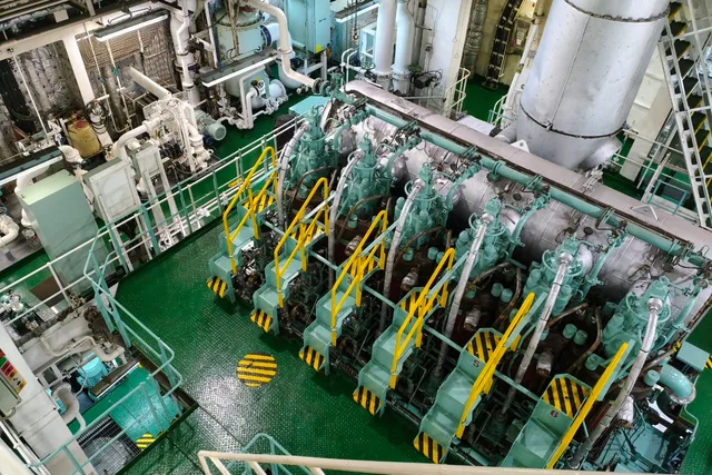
Six-cylinder main engine from the upper platform: cylinder units in a row under the lagged exhaust receiver
Our photo: a six-cylinder main engine from the upper platform
Typical RFQ lines
  • Cylinder liners, piston crowns and piston rings
  • Exhaust valves, spindles and seats
  • Fuel pumps, injectors and nozzles
  • Main, crankpin and crosshead bearing shells
  • Overhaul gasket and seal kits
Send with the request
  • Full engine designation and engine serial number
  • Cylinder number for liner, bearing and fuel-pump lines
  • Part number, part-book page or drawing
  • Photos of the removed part and its markings
System 02

Turbocharger

Driven by the engine's exhaust gas, the turbocharger compresses the charge air the engine burns its fuel with. A main engine usually carries one or two large units; each auxiliary engine has its own.

Connected circuits
Lube oil
Typical RFQ lines
  • Rotor and cartridge assemblies
  • Nozzle rings and diffusers
  • Bearings, bushes and seals
  • Compressor wheels
  • Filter silencers and casing parts
Send with the request
  • Turbocharger maker and type from its own nameplate
  • Turbocharger serial number
  • Engine maker, model and application (main or auxiliary)
  • Part number or drawing position
System 03

Auxiliary engines (gensets)

Medium- or high-speed diesel engines driving generators, usually three or more, supply the ship's electrical power. Builders often fit them from a different maker than the main engine.

Connected circuits
Fuel oilLube oilCooling waterStarting air
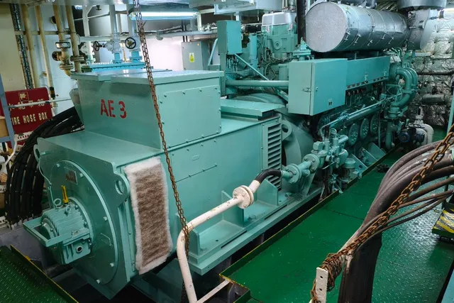
Generator set stencilled AE 3: alternator in front, diesel engine behind on a common bedplate
Our photo: generator set AE 3, engine and alternator on one bedplate
Typical RFQ lines
  • Cylinder heads, valves and seats
  • Pistons, rings and liners
  • Fuel injection pumps and injectors
  • Turbocharger and cooler parts
  • Gasket and overhaul kits
Send with the request
  • Engine maker, model and serial number
  • Generator set position (No. 1, 2, 3) where parts differ
  • Part number or part-book page
  • Nameplate photos of engine and generator
System 04

Separators (purifiers)

Centrifugal separators clean fuel oil and lubricating oil on board, removing water and solids before the oil reaches the engines.

Connected circuits
Fuel oilLube oil
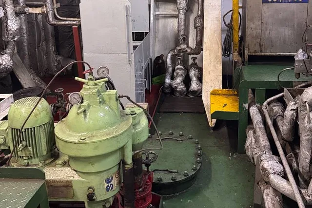
A centrifugal separator close up: bowl hood, drive motor, pressure gauges and the vertical discharge line
Our photo: a separator, bowl hood and drive motor
Typical RFQ lines
  • Disc stacks and bowl parts
  • Gravity discs
  • Bowl seals, O-rings and service kits
  • Operating water and discharge parts
  • Drive parts, couplings and friction pads
Send with the request
  • Separator maker, model and serial number
  • Bowl or service kit reference
  • Duty: fuel oil, lube oil or diesel oil
  • Gravity disc inside diameter where one is fitted
System 05

Pumps

Centrifugal pumps move sea water, fresh water and ballast; fuel is handled by screw or gear pumps, and main-engine lubricating oil by screw or centrifugal pumps. Most systems carry a duty pump and a standby.

Connected circuits
Cooling waterLube oil
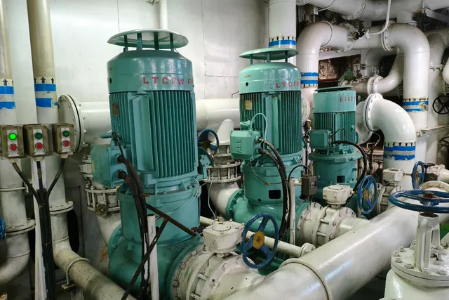
Three vertical in-line pumps on a common header, two motors stencilled LTCFW
Our photo: vertical pumps named by service, not by maker
Typical RFQ lines
  • Impellers and wear rings
  • Mechanical seals
  • Shafts, sleeves and bearings
  • Screw sets for screw pumps
  • Casing gaskets and O-rings
Send with the request
  • Pump maker, model and serial number
  • System and duty: sea water, lube oil, fuel
  • Seal type and shaft diameter for seal lines
  • Nameplate photo
System 06

Coolers and heat exchangers

Plate and shell-and-tube heat exchangers cool the engines' fresh water and lubricating oil, usually through a central cooler that passes the heat to sea water.

Connected circuits
Cooling waterLube oil
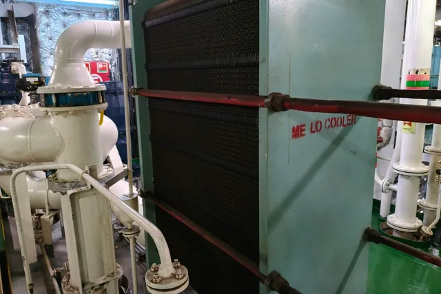
Gasketed plate cooler with the frame stencilled ME LO COOLER and tightening bolts along the pack
Our photo: a plate cooler on main-engine lube oil
Typical RFQ lines
  • Plates and gaskets for plate heat exchangers
  • Tube bundles and end covers
  • Gasket kits
  • Frame and tightening parts
Send with the request
  • Maker, model, frame size and unit serial number
  • Plate count and plate material
  • Gasket material, glued or clip-on, and service side
  • Nameplate photo
System 07

Boiler and exhaust-gas economiser

An oil-fired auxiliary boiler and an exhaust-gas economiser in the funnel casing raise steam for fuel heating and the accommodation; at sea the economiser recovers heat from the main engine's exhaust.

Connected circuits
Fuel oil
Typical RFQ lines
  • Burner parts and atomisers
  • Gauge glasses and level fittings
  • Safety valves
  • Refractory
  • Feed water pump parts
Send with the request
  • Boiler maker, model and serial number
  • Burner maker and model
  • Atomiser marking: flow and spray angle
  • Photos of the part and its plate
System 08

Air compressors and receivers

Main air compressors charge the starting-air receivers that start the main and auxiliary engines; working and control air usually comes from separate compressors.

Connected circuits
Starting air
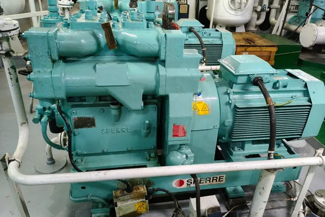
Sperre air compressor and its motor on a common bedplate, SPERRE cast into the crankcase
Our photo: a Sperre air compressor in service
Typical RFQ lines
  • Suction and delivery valves
  • Pistons, rings and liners
  • Bearings and connecting rod parts
  • Coolers and unloaders
  • Overhaul gasket kits
Send with the request
  • Compressor maker, model and serial number
  • Stage and valve position for valve lines
  • Part number or part-book page
  • Nameplate photo
System 09

Switchboard and control room

The main switchboard distributes generator power through air and moulded-case circuit breakers; the engine control room holds the alarm, monitoring and governor equipment.

Typical RFQ lines
  • Circuit breakers and trip units
  • AVRs and protection relays
  • Governors and actuators
  • Sensors, transmitters and gauges
  • Control and alarm modules
Send with the request
  • Breaker type and rated current from the plate
  • Trip unit or relay type
  • Panel or tag number
  • Photo of the plate and the installed position
System 10

Oily water separator

Treats bilge water so it can be discharged within the MARPOL limit of 15 ppm; a 15 ppm bilge alarm, also called an oil content meter, monitors the discharge and stops it if the limit is exceeded.

Typical RFQ lines
  • Filter and coalescer elements
  • Oil content meter parts
  • Pumps and solenoid valves
  • Seals and gasket kits
Send with the request
  • Separator maker, model and serial number
  • Bilge alarm (oil content meter) maker and type
  • Part number or manual page
  • Photo of the unit plate
System 11

Fresh water generator

A vacuum evaporator that makes fresh water from sea water, heated by the main engine's jacket cooling water.

Connected circuits
Cooling water
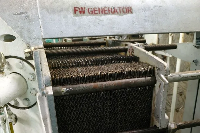
Plate pack of a freshwater generator, the top beam stencilled FW GENERATOR
Our photo: the plate pack of a freshwater generator
Typical RFQ lines
  • Plate packs and gaskets
  • Ejector and ejector pump parts
  • Salinometer parts
  • Valves and vacuum fittings
Send with the request
  • Maker, model and serial number
  • Plate type and plate count
  • Part number or manual page
  • Nameplate photo
System 12

Steering gear

A hydraulic ram or rotary-vane steering gear in the steering gear room turns the rudder stock on orders from the bridge.

Typical RFQ lines
  • Hydraulic pumps and pump parts
  • Ram seals or vane seals
  • Valves and valve blocks
  • Feedback and control units
  • Seal and gasket kits
Send with the request
  • Maker, type (ram or rotary vane) and serial number
  • Pump unit model
  • Part number or drawing
  • Photo of the plate

Maker names identify equipment only. Vessel Core OÜ is an independent supplier; availability, documents and the supply route are confirmed for each RFQ. Photographs in the system cards are our own, taken aboard vessels during yard and client visits; a maker is named only where its name is on the machine.

Questions

About the drawing

Is this drawing of a specific ship?

No. It is a generic engine-room layout drawn to explain the systems. Real arrangements vary with ship type, builder and engine choice, so treat positions as illustrative.

Does Vessel Core supply parts for every system shown?

Each system links to the pages where we describe the equipment families we work with. Availability, documents and the supply route for a specific part are confirmed at RFQ review, not in advance.

My equipment is not on the drawing. Can I still send an RFQ?

Yes. Send the maker, model, serial number and a nameplate photo. A request can also start without a part number.